Tauro Cat1 Gateway
This guide covers the initial setup for the Tauro Cat1 Gateway. The gateway can be used as a standalone device with USB-C charging, or paired with the Tauro Gateway 5W Solar Panel Kit for field deployment.
Contents
- What's in the Box
- Connect the Battery
- Connect the Antennas
- Install the 5W Solar Panel Kit
- Mount the Gateway
- Troubleshooting
What's in the Box
The Tauro Cat1 Gateway package includes:
- 1 x Tauro Cat1 Gateway
- 2 x white 4G antennas
- 1 x grey BLE/Wi-Fi antenna
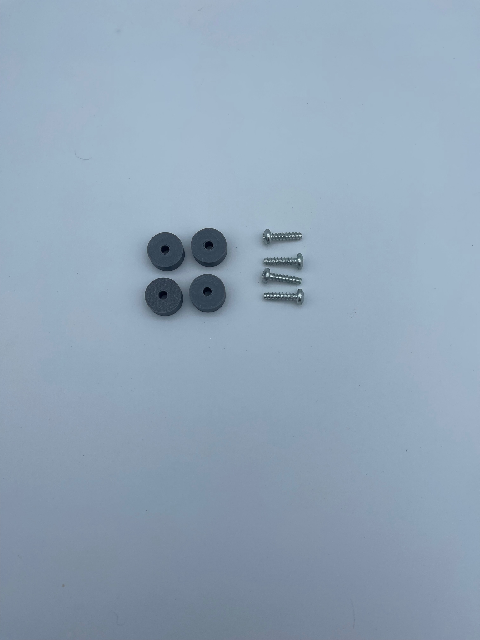
The optional Tauro Gateway 5W Solar Panel Kit includes:
- 1 x 5W solar panel and mounting bracket
- 4 x M4x16mm screws
- 4 x spacers
Connect the Battery
The gateway is shipped with the battery disconnected.
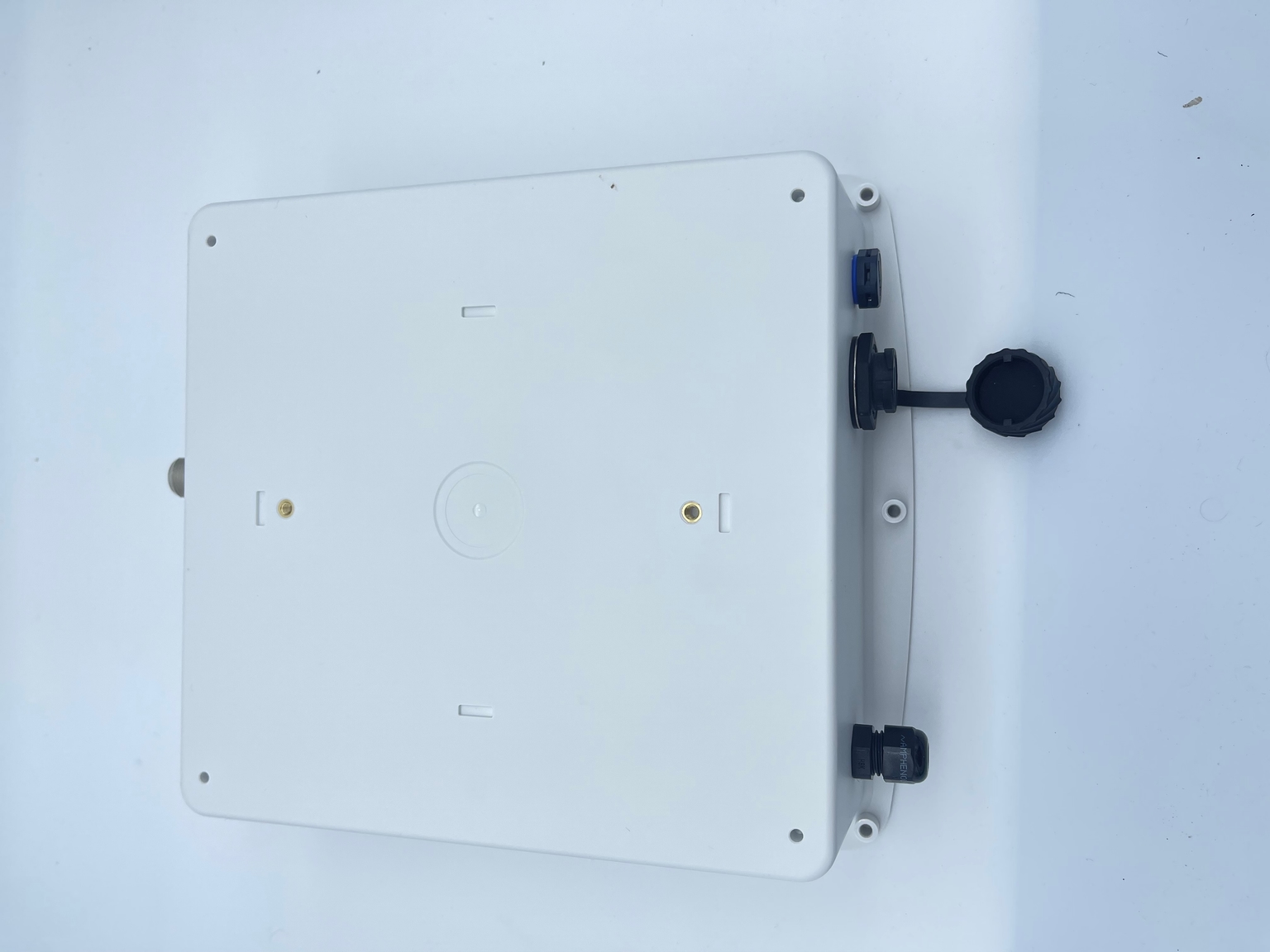
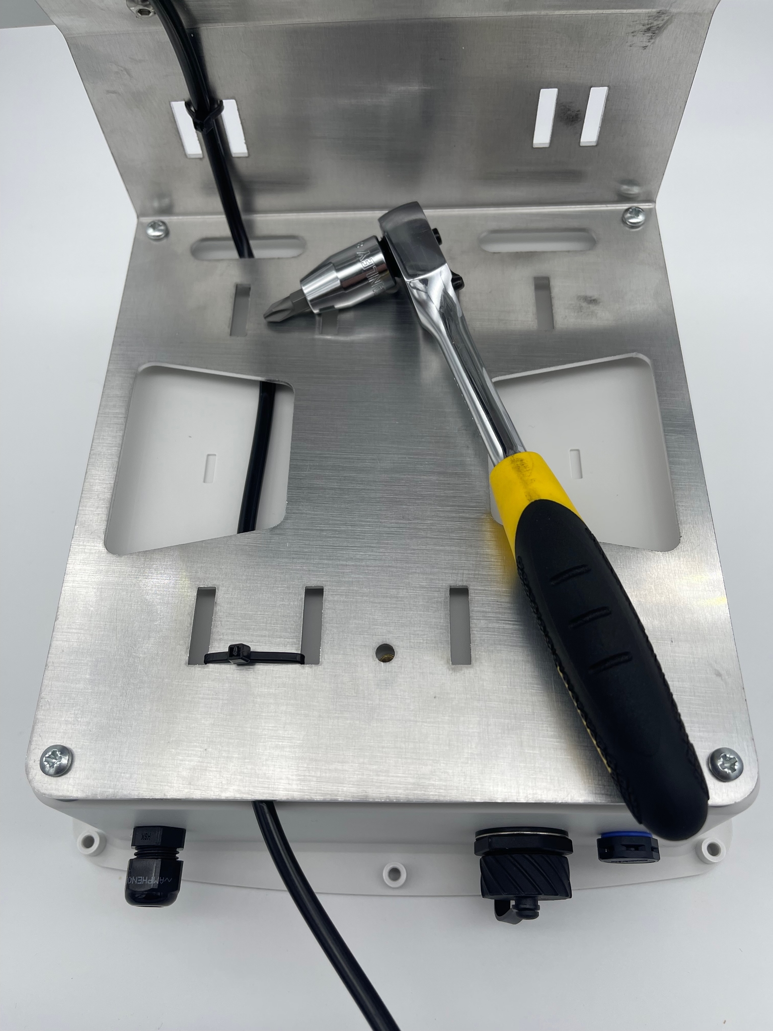
- Place the gateway on a clean work surface.
- Undo the screws holding the front cover in place.
- Remove the cover carefully so the internal wiring is not pulled.
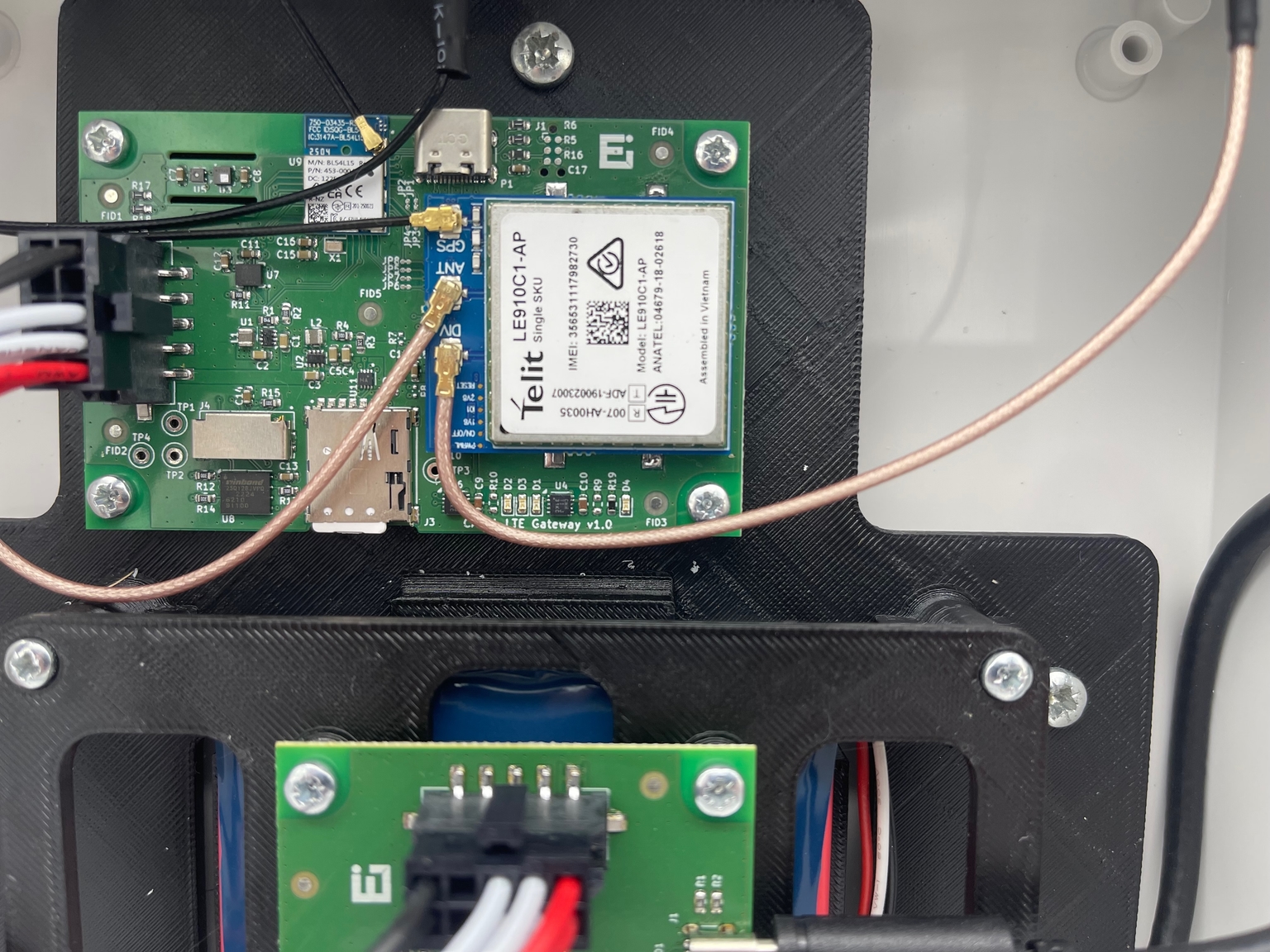
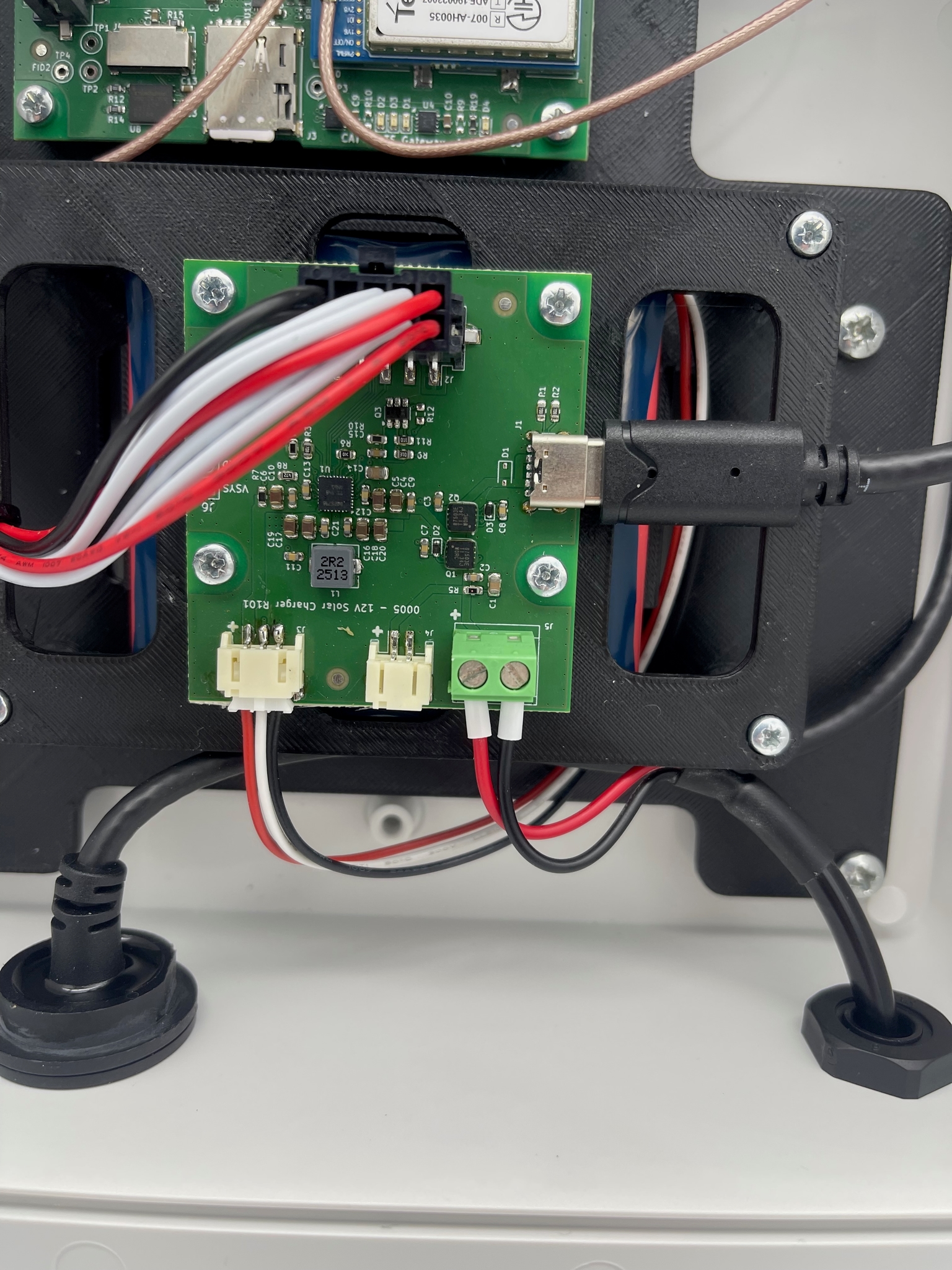
- Plug the battery connector into the battery controller board.
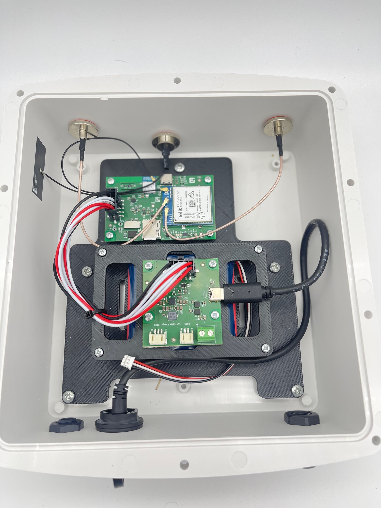
Once the battery is connected, the main controller board with the Cat1 modem will blink a few times during startup.
The status LED indicates the LTE connection state:
- Red flashing: the gateway has not established an LTE connection.
- Green flashing: the gateway has established an LTE connection.
After the battery is connected and the startup LED sequence has been checked, reinstall the front cover and tighten the screws evenly.
Connect the Antennas
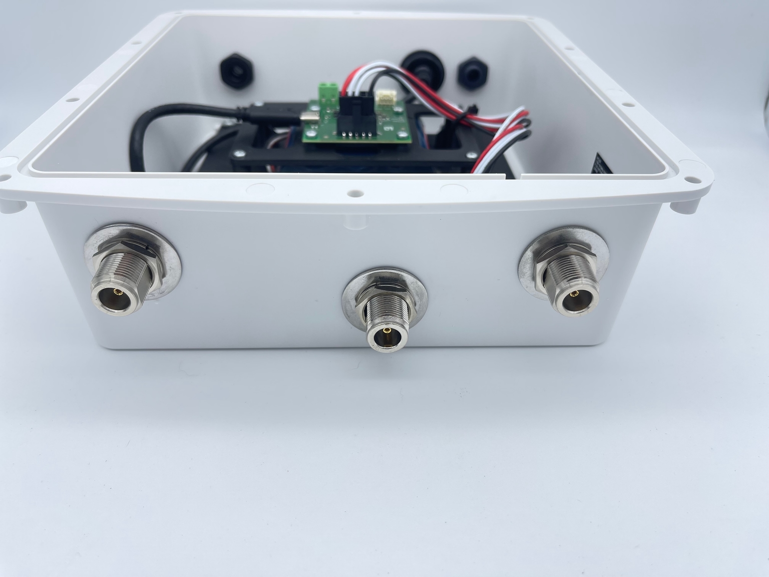
The gateway has three N-Type antenna connectors on the front panel.
- Screw the two white 4G antennas onto the two outer N-Type connectors.
- Screw the grey BLE/Wi-Fi antenna onto the middle N-Type connector.
- Tighten each antenna by hand until secure.
Install the 5W Solar Panel Kit
The Tauro Gateway 5W Solar Panel Kit mounts to the back of the gateway enclosure.
- Place the solar panel bracket against the back of the gateway case.
- Fit the provided spacers between the bracket and the case.
- Attach the bracket using the 4 provided M4x16mm screws.
- Tighten the screws evenly so the panel is secure.
Connect the solar panel cable to the battery controller board:
- Feed the solar panel cable into the gateway enclosure.
- Insert the red wire into the positive screw terminal on the battery controller board.
- Insert the black wire into the negative screw terminal on the battery controller board.
- Tighten both screw terminals and lightly check that each wire is secure.
Mount the Gateway
Before mounting the gateway:
- Confirm the battery is connected.
- Confirm the front cover is screwed down tightly.
- Confirm all three antennas are attached in the correct positions.
- If using the solar kit, confirm the panel is fixed to the back of the case and the solar cable is connected to the battery controller board.
- Wait for the LTE status LED to change from red flashing to green flashing.
Once these checks are complete, the gateway is ready to mount.
Troubleshooting
- No LED activity after connecting the battery: check that the battery connector is fully seated on the battery controller board.
- LED keeps flashing red: move the gateway to an area with better LTE coverage and confirm the two white 4G antennas are connected to the outer N-Type connectors.
- Solar charging is not working: check that the red and black solar panel wires are connected to the correct screw terminals and are held securely.
- Antenna does not fit: confirm the two white 4G antennas are on the outer connectors and the grey BLE/Wi-Fi antenna is on the middle connector.